
In Part 1 of our Miami Bridge failure series we discussed how re-tensioning Member 11, undertaken to close cracks in the concrete, led to the bridge’s sudden collapse.
24 February 2018 – Concrete Casting
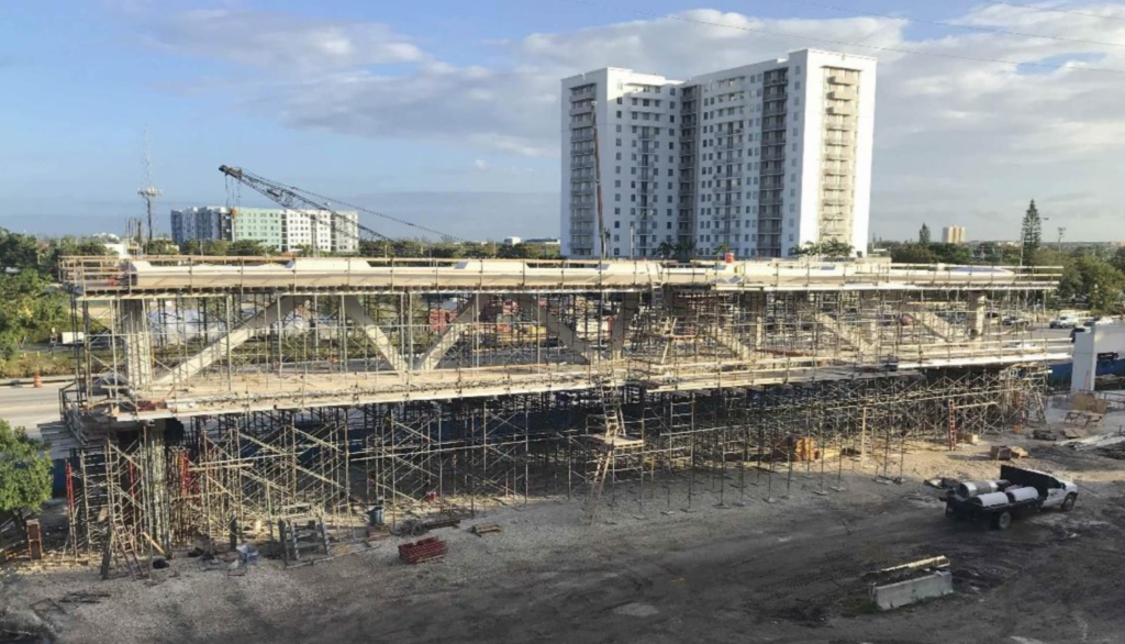
The main span of the bridge was cast near the site and then moved to its location over the freeway. During casting it was supported by temporary falsework, but once the concrete had gained sufficient strength, this falsework was removed.
While this removal was occurring on 24 February, and the bridge began to support its own weight for the first time, workers heard a very loud and distinctive cracking sound.
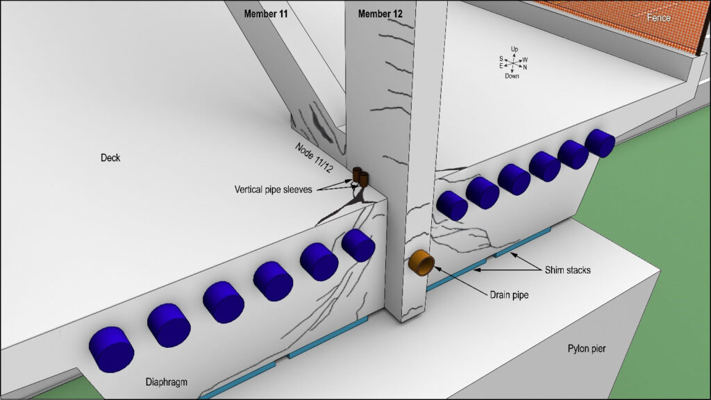
The structure was inspected, and cracks were found around Member 11, the very same area that would blowout on the day of the failure.
On 28 February, photographs of these cracks were taken by Bolton, Perez and Associates Consulting Engineers, who were engaged by the Florida International University as the construction engineering and inspection contractor (CEI). It was their job to ensure work was progressing according to plan, and when they saw these cracks they were concerned. They passed the photographs onto MCM, the design and build contractor of the structure, who in turn passed them onto FIGG Bridge Engineers, the designers of the bridge. MCM sought comments from FIGG regarding what to do about the cracks. FIGG employed the engineer of record, who was ultimately responsible for the safety of the bridge.
But cracks in concrete structures are not uncommon, and they generally don’t cause concern if they’re less than 0.4 mm wide. That’s the average thickness of a human nail. If you’re getting cracks larger than this, you may have a problem, and these cracks were considerably larger than the thickness of a nail.


Despite being sent the photographs on 28 February, FIGG didn’t reply until 7 March, and despite the size of the cracks, FIGG said they were of no concern.
10 March 2018 – 5 Days Prior to Failure
On 10 March 2018 the main span was being moved to its final position over the freeway, but before this could happen, Members 2 and 11 had to be post-tensioned.
This was a consequence of how the span would be supported during transportation – the transporter supports would be located below Members 3 and 10, which would result in the ends of the bridge hanging downwards, which would induce tension in Members 2 and 11. As we discussed in Part 1, concrete is poor at carrying tensile loads, and the post-tensioning was meant to prevent cracking in these members.
Once the bridge was placed on its supports over the freeway, it would be spanning from end to end, and Members 2 and 11 would be in compression. The post-tensioning would no longer be required and the members would be de-tensioned.

So on 10 March, the SPMTs (Self Propelled Modular Transporters) lifted the 950 ton structure and, over an 8 hour period, moved it to its final position over the freeway. The freeway was closed to traffic during this exercise.

The SPMT supports were then removed, and the de-tensioning of Members 2 and 11 began. But as the de-tensioning progressed, cracks began to appear and get worse at a number of locations, including around Member 11. One of the contractors undertaking the de-tensioning became visibly disturbed by this cracking, and he took photographs. He sent them to his supervisor, saying, “it cracked like hell”.
12 March 2018 – 3 Days Prior to Failure
Two days later, on March 12, MCM documented the crack development around Member 11, and at 4.51 pm sent photographs to FIGG. MCM said the cracks were concerning, and they request FIGG review and advise the best course of action.
13 March 2018 – 2 Days Prior to Failure
FIGG opened the email at 7:45 am the following morning, 13 March. At 9:30 am they called MCM to discuss the cracks, but there was some confusion over when the photographs of the cracks were taken. Fifteen minutes later FIGG emailed MCM and discussed possible remedial actions, but stated: “We do not see this as a safety issue”.
At 10:59 am, MCM received a report from Bolton, Perez & Associates (the CEI) again raising the issue of the cracks. They recommend monitoring them.
At 4:13 pm FIGG left a voicemail for the Florida Department of Transport, updating them and saying the cracks were probably due to the de-tensioning of the members. (As we now know, the de-tensioning of Member 11 made these cracks worse, but they had existed and were known to FIGG since 28 February.)
At 5:00 pm FIGG called MCM and proposed a remedial measure – Member 11 should be re-tensioned to close some of the cracks. FIGG then followed up with an email at 5:18 pm confirming the voicemail, and added: “Again, we have evaluated this further and confirmed that this is not a safety issue.”
14 March 2018 – 1 Day Prior to Failure
But just how bad were these cracks at this point? Should they have raised concerns?
As we discussed earlier, crack widths above 0.4 mm are of concern, but by this point, 14 March, some of the cracks were more than 40 times larger than this limit. And not only were they larger, they were extensive around Member 11, they were visually distressing, and they were clearly structural cracks – they were a consequence of the bridge being unable to carry its own self weight. This was a bridge exhibiting significant distress, with the crack widths suggesting the reinforcing steel beneath was yielding.
In the words of the NTSB investigation report: “The extensive, large, and wide cracks observed in the member 11/12 nodal region should have been recognized as being abnormal for a reinforced concrete structure.” This was the “bridge screaming at everyone that it was failing”.
Look at the cracks in the photograph below, which was taken two days before the failure by MCM (at Member 2). Try convincing yourself it’s thinner than your nail and not of concern. This crack was also 3 to 4 inches (75 – 100 mm) deep.

15 March 2018 – Day of the Failure
A meeting was scheduled for 9 am on 15 March. FIGG planned to deliver a presentation on the cracking to a range of parties. Prior to this meeting, at 8 am, the FIGG engineer of record and another employee visited the bridge, inspected the cracks at Member 11, and took a number of photographs (see below).


Then, just prior to the presentation at the 9 am meeting, MCM showed the FIGG engineers some additional photographs they’d taken of the cracks. MCM told FIGG that these “cracks look more significant in person than on the photographs”.
FIGG then delivered their presentation to the project’s major parties: the Florida International University, the Florida Department of Transport, MCM, and Bolton Perez. They again stressed there were no safety concerns – despite having visited the bridge that morning, despite having inspected the cracks, and despite having MCM provide additional photographs and express concern. FIGG’s minutes from the meeting stated: “Based on the discussions at the meeting, no one expressed concern with safety of the span suspended over the road”.
FIGG said preparations for the re-tensioning of Member 11 were ongoing and it would take place immediately. It appeared that the FIGG engineer of record’s view was that re-applying the tension to this member would pull the concrete back together and close the cracks. They believed this would bring the bridge back to its pre-existing condition prior to it leaving the casting yard.
Now this was never going to happen – the structure had experienced significant distress, there was clear evidence of plastic, as opposed to elastic, deformations – cracked concrete and yielded steel reinforcing would never return the structure to its pre-existing condition. This extensive cracking proved there was an issue with the bridge – it was simply not behaving as it was supposed to, and no one at the meeting seemed willing to call the situation for what it was.
The Decision
How did it ever come to this?
Why did the extensive cracking not result in a halt to construction? Why didn’t FIGG recognise they clearly had a design error with their bridge? Why did the peer review of the bridge design miss this error? And why, despite having all the authority to do so, did no one close the road during the re-tensioning procedure? Why did it occur over live traffic?
In Part 3 we’ll tackle these questions but, as you’ll find out, there will be no easy answers.
All photographs taken from the NTSB investigation report or the U.S Department of Labor report.